
Generador de pulso V4.11 · Ficha de datos
Quick reference
Application
The Pulse Generator for RITTER Drum-type Gas Meters and Bellows-type Gas Meters is a rotary encoder for pulse output. It can be used to transfer the measured gas volume for remote display and/or data processing (calculation of flow rate, data transfer via RS232) to the Electronic Display Unit »EDU 32 FP« (accessory) or to an external measuring system / PC. In the latter case, the external system must provide the power supply (5 – 24 V) for the photo sensor as well as the evaluation circuit/logic which enables the direct readout of the measured volume and flow rate. For connection to an external system, please refer to »Electrical Data« and the wiring diagrams.
Components
The Pulse Generator is located within the housing of the counter mechanism of the Gas Meter (behind the dial plate) and it consists of the following components:
Description
The measuring drum of drum-type meters and the measuring unit of bellow-type meters are coupled 1:1 to the slit disc via a magnetic coupling. The optical encoding bars of the film disc rotate through the U-shaped photo sensor, thereby interrupting the light beam of the photo diode intermittently. Thus, the photo interrupter converts the revolution of the measuring drum into a sequence of pulses. The number of pulses represents the volume of gas which has passed through the Gas Meter, depending on the respective resolution (see »Performance Data«). The frequency of the sequence of pulses is a measure of the rotational speed of the measuring drum and thereby a measure of the flow rate of the gas.
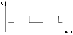
For operation of the photo sensor, an external electric power supply in the range of 5 – 28 Volts DC is required. The output signal is a TTL signal, whereby the pulse level (= min./max. voltage of the signal) depends on the power supply voltage and current load (please refer to »Electrical Data«).
For power supply values between 5 and 28 Volts, the output signal level can be linearly interpolated for the first approximation.
Output Socket
The pin configuration of the 5-pin output socket is shown under »Pin configuration of the Output Socket«.
Use with Drum-type Gas Meters
Drum-type gas meters are volumetric gas meters. That means, that they are measuring gas volume precisely. When the Pulse Generator is used with drum-type gas meters for recording the gas flow, it is possible for the respective Voltage Output curve (line) to be wavy, even when gas flow is constant. This is (unpreventably) caused by the type of construction of the measuring drum: the drum consists of four separate chambers, which are closed and opened in sequence. The previous chamber has to be closed before the next chamber will open.
This compulsory measurement is the reason for the high measurement accuracy. However, each closing also causes a little build-up of pressure at the inside of a chamber. The surface tension creates an additional pressure increase during emerging of a chamber (water highest surface tension, oil: lower, CalRix lowest). The resulting pressure increase causes a small reduction in the rotational speed of the measuring drum. This is barely visible to the eye but is documented precisely by a computer/transcriber. Thus, the wavy output line at constant input flow documents the true flow through the gas meter.
Performance Data
| Gas Meter (Type) | Pulses per Revolution* (P/R) | Gas Flow per Revolution* (ltr/R) | Resolution (ltr/Pulse) | Pulses per Liter (Pulse/ltr) | Maximum Pulse Frequency (Pulse/min) |
|---|---|---|---|---|---|
| TG 01 | not applicable | ||||
| TG 05 | 500 | 0.5 | 0.001 | 1,000.0 | 1,000 |
| TG 1 | 500 | 1.0 | 0.002 | 500.0 | 1,000 |
| TG 3 | 500 | 3.0 | 0.006 | 166.7 | 1,000 |
| TG 5 | 500 | 5.0 | 0.010 | 100.0 | 1,000 |
| TG 10 | 500 | 10 | 0.020 | 50.0 | 1,000 |
| TG 20 | 500 | 20 | 0.040 | 25.0 | 1,167 |
| TG 25 | 500 | 25 | 0.050 | 20.0 | 2,333 |
| TG 50 | 500 | 50 | 0.100 | 10.0 | 3,000 |
| BG 4 | 500 | 10 | 0.020 | 50.0 | 5,000 |
| BG 6 | 500 | 20 | 0.040 | 25.0 | 4,167 |
| BG 10 | 500 | 50 | 0.100 | 10.0 | 2,667 |
| BG 16 | 500 | 100 | 0.200 | 5.0 | 2,083 |
| BG 40 | 500 | 100 | 0.200 | 5.0 | 5,417 |
| BG 100 | 500 | 100 | 0.200 | 5.0 | 13,333 |
* TG types: Revolution of measuring drum ( = revolution of large Needle of dial plate) / BG types: Revolution of large Needle of dial plate
Temperature range
Dimensions of encoding disc
| TG05 to TG50 / BG | |
|---|---|
| Diameter | 144 mm |
| Slit width | 0.492 mm |
| Bar width | 0.356 mm |
Electrical Data
| Supply Voltage | Us | 5 – 28 V DC | |
| Supply Current | Us = 5 V | < 2 mA | |
| Us = 28 V | < 4 mA | ||
| Voltage Output | Us = 5 V, no load | high level | 4.95 V |
| Us = 5 V, load ISource 4.7 mA | high level | 3.56 V | |
| Us = 5 V, no load | low level | 0.01 V | |
| Us = 5 V, load ISink7 mA | low level | 1.05 V | |
| Us = 28 V, no load | high level | 26.8 V | |
| Us = 28 V, load ISource 7 mA | high level | 26.5 V | |
| Us = 28 V, no load | low level | 0.01 V | |
| Us = 28 V, load ISink 7 mA | low level | 1.2 V | |
| Current Output | Us = 5 V | source | 4.7 mA |
| Us = 28 V | source | 7 mA | |
| Us = 5 – 28 V | sink | 7 mA | |
| Operating frequency photo diode | 0 – 500 Hz |
Specifications
Pin configuration of the Output Socket
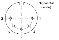
3 → Supply Voltage US2 (red)
5 → Supply Voltage US1 (red)
2 → none
4 → Signal Out (white)
1 → GND (black)
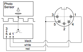
Internal wiring
Signal Output
| Pin No. | Function | Lead Colour | |
|---|---|---|---|
| Photo Sensor | 3 + 5 | Supply Voltage US1 + US2 | red |
| 4 | Signal Out | white | |
| 1 | Ground | black |
Attention: The mini plug of the cable which connect the sensor and the output socket must be mounted to the sensor in the shown position. Especially the red leads must be connected to the pin close to the corner of the sensor casing.
Otherwise the sensor will be destroyed!
Connection of Electronic Display Unit »EDU 32 FP« (optional accessory) to the Pulse Generator
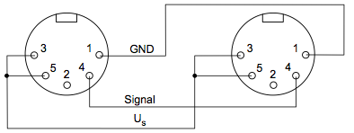
The Pulse Generator can be connected to the optional accessory »Electronic Display Unit« (V 5.0 or higher) by means of the 5-pin connection cord, which is supplied in conjunction with the Electronic Display Unit. The maximum possible length of the connection cable is 10 m (unshielded cable) or 100 m (shielded cable). The Electronic Display Unit contains the power supply for the photo sensor as well as the evaluation circuit/logic which enables the direct readout of the measured volume (ltr) and flow rate (ltr/h).
The measurement results displayed by the Electronic Display Unit can be transmitted to a computer via the standard-type interface RS 232 (please refer to the EDU Operation Instructions, paragraph 7.3 as well). Additionally, the value of the flow rate can be transmitted to an analog measurement device via the standard-type analog output (0 – 1 Volt or 4 – 20 mA).
Wiring of the Pulse Generator to the EDU socket
Set-up of EDU
V 4.11 / Rev. 2023-03-09 / Sujeto a modificaciones.
https://dlr.ritter.de/es/generador-de-pulso-v411/
Dr.-Ing. RITTER Apparatebau GmbH & Co. KG · Coloniastrasse 19-23 · D-44892 Bochum · Alemania
Si tiene preguntas, comuníquese con mailbox@ritter.de o su socio de distribución local (en nuestra página de resumen)